
CSE306: Computer Networks
Module 2 The Network Layer
⭐The Network Layer
1. Overview of Local Area Network (LAN) Communication:
Communication through MAC Addresses:
- Nodes on a LAN communicate using their physical MAC addresses.
- This method works effectively in small-scale networks.
Role of Switches:
- Switches learn MAC addresses associated with each port.
- They use this information to route transmissions efficiently.
2. Limitations of MAC Addressing:
Scalability Issues:
- MAC addresses are unique to each network interface but lack systematic ordering.
- The global spread of MAC addresses is not easily traceable.
Challenges for Long-Distance Communication:
- MAC addressing is not ideal for communication across wide distances.
- It’s challenging to determine the location of a MAC address globally.
3. Address Resolution Protocol (ARP):
- Purpose of ARP:
- ARP is used for mapping IP addresses to MAC addresses within a single network segment.
- It is not suitable for translating physical addresses across different network segments.
4. Introduction to the Network Layer:
Need for a Different Solution:
- The network layer provides a solution for addressing and routing beyond local networks.
- This is where the Internet Protocol (IP) comes into play.
Internet Protocol (IP):
- IP addresses are used to identify and locate devices across different networks.
- Provides a systematic way of addressing that scales better than MAC addresses.
5. Key Learning Outcomes:
IP Address Identification:
- Ability to identify and understand IP addresses.
IP Datagram Encapsulation:
- Understanding how IP datagrams are encapsulated inside Ethernet frames.
IP Datagram Header Fields:
- Ability to identify and describe the various fields within an IP datagram header.
1) IPv4 Addresses

1. Structure of IPv4 Addresses:
Length and Format:
- IPv4 addresses are 32-bit long numbers.
- They are divided into four octets (8-bit segments).
- Each octet is represented in decimal form.
Decimal Range of Octets:
- Each octet can represent decimal numbers from 0 to 255.
- Example of a valid IP address:
12.34.56.78. - Example of an invalid IP address:
123.456.789.100(numbers exceed the 0-255 range).
Notation:
- The decimal representation of IP addresses is known as dotted decimal notation.
2. Distribution and Hierarchy:
IP Address Allocation:
- IP addresses are distributed to organizations and companies, not determined by hardware vendors.
- This distribution is hierarchical and organized for efficient management.
Example of Hierarchical Distribution:
- IBM owns IP addresses where the first octet is
9. - For instance, an IP address like
90.0.0.1would be directed to one of IBM’s routers. - IBM’s router handles the further routing of the data packet.
- IBM owns IP addresses where the first octet is
3. IP Addresses vs. MAC Addresses:
Network Ownership:
- IP addresses are assigned to networks, not individual devices.
- Unlike MAC addresses, which are fixed and tied to hardware, IP addresses can change based on network context.
Dynamic vs. Static IP Addresses:
Dynamic IP Addresses:
- Assigned automatically through Dynamic Host Configuration Protocol (DHCP).
- Common for client devices (e.g., laptops, smartphones).
- IP address can change as the device connects to different networks.
Static IP Addresses:
- Manually configured on a node.
- Typically used for servers and network devices.
- The IP address remains constant regardless of network changes.
2) IPv4 Datagram and Encapsulation
1. IP Datagram Overview:
Definition:
- An IP datagram is the packet used at the network layer under the IP protocol.
- It consists of a header and a payload.
Comparison to Ethernet Frames:
- Just as Ethernet frames have a defined structure, IP datagrams also have a structured format.

2. IP Datagram Header:
Version Field (4 bits):
- Indicates the version of IP being used (e.g., IPv4, IPv6).
- Most common version: IPv4.
Header Length Field (4 bits):
- Specifies the length of the IP header.
- Typically 20 bytes for IPv4, which is the minimum header length.
Service Type Field (8 bits):
- Used to specify quality of service (QoS) details.
- Helps routers prioritize and manage IP datagrams.
Total Length Field (16 bits):
- Indicates the total length of the IP datagram (header + payload).
- Maximum size of a datagram is 65,535 bytes (largest number representable with 16 bits).
Identification Field (16 bits):
- Used to group fragments of a datagram.
- Essential for reassembling fragmented datagrams.
Flags Field:
- Indicates whether a datagram can be fragmented or if it has already been fragmented.
Fragmentation Offset Field:
- Provides information on where the fragment fits within the original datagram.
- Used for reassembling fragmented packets.
Time to Live (TTL) Field (8 bits):
- Limits the number of router hops a datagram can make.
- Each router decrements the TTL value by one.
- Prevents datagrams from looping indefinitely due to routing errors.
Protocol Field (8 bits):
- Specifies the transport layer protocol used (e.g., TCP, UDP).
Header Checksum Field:
- A checksum of the IP datagram header for error-checking.
- Changes with each router since the TTL value is decremented.
Source IP Address Field (32 bits):
- Contains the IP address of the sending device.
Destination IP Address Field (32 bits):
- Contains the IP address of the receiving device.
IP Options Field:
- Optional field for special settings or testing purposes.
- Variable length and usually followed by padding.
Padding Field:
- Added to ensure the header is of the correct total size.
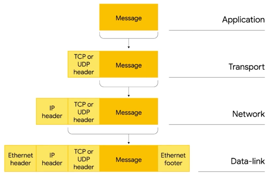
3. Encapsulation:
Concept:
- Encapsulation is the process where an IP datagram is placed inside the payload of an Ethernet frame.
- This means that the entire IP datagram is transmitted as part of an Ethernet frame.
IP Datagram Payload:
- The payload of the IP datagram contains the actual data, which could be a TCP or UDP packet.
4. Layered Networking:
- Role of Each Layer:
- Understanding the structure of IP datagrams and encapsulation highlights the importance of layered networking.
- Each layer (network, transport, data link) builds upon the layer below it to provide comprehensive communication functionality.
3) IPv4 Address Classes

1. Structure of IP Addresses:
- Network ID and Host ID:
- IP addresses are divided into two parts: the network ID and the host ID.
- Example: For IP address
9.100.100.100:- Network ID: First octet (
9) - Host ID: Remaining three octets (
100.100.100)
- Network ID: First octet (
2. Address Class System:
Purpose:
- Defines how the global IP address space is organized.
- Determines the division between network and host IDs.
Primary Address Classes:
Class A:
- Network ID: First octet
- Host ID: Last three octets
- Network Size: 2^24 (16,777,216 addresses)
- First Octet Range: 0-127
- Binary Prefix:
0
Class B:
- Network ID: First two octets
- Host ID: Last two octets
- Network Size: 2^16 (65,536 addresses)
- First Octet Range: 128-191
- Binary Prefix:
10
Class C:
- Network ID: First three octets
- Host ID: Last octet
- Network Size: 2^8 (256 addresses)
- First Octet Range: 192-223
- Binary Prefix:
110

3. Additional Address Classes:
Class D:
- Purpose: Used for multicasting.
- First Octet Range: 224-239
- Binary Prefix:
1110
Class E:
- Purpose: Reserved for experimental use and testing.
- First Octet Range: 240-255
- Binary Prefix:
1111
4. Practical Usage:
CIDR (Classless Inter-Domain Routing):
- Replaces the traditional class system for more flexible IP address allocation.
- Allows for more efficient use of IP address space.
Relevance:
- While CIDR is the current standard, understanding the class system remains important for foundational networking knowledge.
⭐Subnetting

1. Overview of Subnetting:
- Definition:
- Subnetting is the process of dividing a large network into smaller, more manageable subnetworks or subnets.
- Objective:
- Improves network management and efficiency.
- Addresses the issue of having too many devices connected to a single router.
2. Importance of Subnetting:
- Need for Subnetting:
- A single Class A network (e.g.,
9.0.0.0) contains 16,777,216 IP addresses. - Managing such a large network with a single router is impractical.
- A single Class A network (e.g.,
- Solution:
- Subnetting splits the large network into smaller subnets, each with its own gateway router.

3. Network and Host IDs:
- Basic Structure:
- An IP address is divided into a network ID and a host ID.
- Limitation:
- Basic network and host ID structure might be insufficient for large networks.
4. Subnet Masks:
- Function:
- Subnet masks extend the basic network and host ID structure.
- Define the boundary between the network and subnet portions of an IP address.
- Usage:
- Enable more precise control over network division and address allocation.
5. CIDR (Classless Inter-Domain Routing):
- Purpose:
- Provides greater flexibility compared to traditional subnetting.
- Mechanism:
- Allows for variable-length subnet masks.
- Facilitates efficient use of IP address space and routing.

6. Binary Math in Subnetting:
- Importance:
- Understanding binary math is crucial for subnetting.
- Helps in calculating subnet masks, determining subnet ranges, and more.
7. Routing and Gateway Routers:
- Routing Process:
- Core routers route messages based on network IDs.
- Gateway routers manage traffic for specific subnets and handle ingress and egress.
- Function of Gateway Routers:
- Serve as the entry and exit points for subnetworks.
- Responsible for routing packets within their respective subnets.
1) Subnet Masks

1. Introduction to Subnet Masks:
- Purpose:
- Subnet masks are used to divide an IP address into network, subnet, and host IDs.
- They extend the basic network and host ID concept to include subnets.
2. Structure of an IP Address:
- Components:
- Network ID: Identifies the network.
- Subnet ID: Further divides the network into subnets.
- Host ID: Identifies individual devices within a subnet.
3. Concept of Subnet Masks:
Binary Representation:
- Subnet masks are 32-bit numbers, often written in decimal as four octets.
- They are split into two sections: a string of ones (mask) and a string of zeros.
Function:
- The part with ones identifies the network and subnet portions of the IP address.
- The part with zeros identifies the host portion.

4. Example:
IP Address: 9.100.100.100
- Binary Representation:
9in binary:0000 1001100in binary:0110 0100
- Full IP address in binary:
0000 1001.0110 0100.0110 0100.0110 0100
- Binary Representation:
Subnet Mask Example: 255.255.255.0
- Binary Representation:
255:1111 11110:0000 0000
- Full subnet mask in binary:
1111 1111.1111 1111.1111 1111.0000 0000 - Mask Part:
1111 1111.1111 1111.1111 1111 - Host Part:
0000 0000
- Binary Representation:
5. Determining Subnet and Host IDs:
Subnet ID:
- Bits corresponding to ones in the subnet mask.
- For
255.255.255.0, the subnet ID is derived from the last octet.
Host ID:
- Bits corresponding to zeros in the subnet mask.
- For
255.255.255.0, the host ID is in the last octet.
6. Subnet Size:
Subnet Mask 255.255.255.0:
- Host ID Space: Last octet (8 bits).
- Number of Possible Addresses: 256 (0-255).
- Usable Addresses: 254 (excluding
0and255).
Subnet Mask 255.255.255.224:
- Binary Representation:
1111 1111.1111 1111.1111 1111.1110 0000 - Number of Host Bits: 5 bits.
- Number of Addresses: 32 (0-31).
- Usable Addresses: 30.

7. CIDR Notation:
- Purpose:
- Provides a shorthand way to denote subnet masks.
- Example:
- Subnet mask
255.255.255.224can be written as/27. - Full notation:
9.100.100.100/27.
2) Basic Binary Math
1. Understanding Binary Numbers
Base Systems:
- Decimal (Base 10): Uses 10 digits (0-9). Each digit represents a power of 10.
- Binary (Base 2): Uses 2 digits (0 and 1). Each digit represents a power of 2.
Counting in Binary:
Binary Sequence:

Columns and Carries:
- Binary counting operates similarly to decimal counting but with only two digits. You add a new column when you reach the maximum value of a column (which is
1in binary, and9in decimal).
- Binary counting operates similarly to decimal counting but with only two digits. You add a new column when you reach the maximum value of a column (which is
2. Calculating Possible Values
- Number of Possible Values:
Formula: , where is the number of bits.
Examples:
- 8 bits: values (0-255)
- 4 bits: values (0-15)
- 16 bits: values (0-65,535)
Base System Comparison:
- Decimal: gives the number of possible values for digits.
- For 2 decimal digits: values (0-99)
- For 3 decimal digits: values (0-999)

3. Binary Arithmetic
Addition:
- Rules:
- 0 + 0 = 0
- 0 + 1 = 1
- 1 + 0 = 1
- 1 + 1 = 10 (carry over 1 to the next column)
- Rules:
Binary Operators:
AND Operator:
- Rules: Returns true (1) if both operands are true (1).
- Examples:
- 1 AND 1 = 1
- 1 AND 0 = 0
- 0 AND 0 = 0
OR Operator:
- Rules: Returns true (1) if at least one operand is true (1).
- Examples:
- 1 OR 1 = 1
- 1 OR 0 = 1
- 0 OR 0 = 0
4. Application in Networking
- Subnet Masks:
Purpose: To determine which part of an IP address identifies the network and which part identifies the host.
Example Calculation:
- IP Address: 9.100.100.100
- Subnet Mask: 255.255.255.0

Binary Representation:
- IP Address in Binary:
0000 1001.0110 0100.0110 0100.0110 0100 - Subnet Mask in Binary:
1111 1111.1111 1111.1111 1111.0000 0000

Binary AND Operation:
- Apply the AND operator to the IP address and subnet mask:
- Result:
0000 1001.0110 0100.0110 0100.0000 0000(which equals9.100.100.0)
- Result:
- Apply the AND operator to the IP address and subnet mask:
Function: This operation determines the network portion of the IP address, helping routers to decide if an IP address is within the same network or needs to be routed elsewhere.
3) CIDR (Classless Inter-Domain Routing)
CIDR, or Classless Inter-Domain Routing, was developed to overcome the limitations of the original class-based IP address allocation system and traditional subnetting. Here’s an in-depth look at CIDR and its advantages:

1. Limitations of Class-Based Addressing
Fixed Sizes:
- Class A Networks: 8-bit network ID, 24-bit host ID (16,777,216 addresses per network).
- Class B Networks: 16-bit network ID, 16-bit host ID (65,534 addresses per network).
- Class C Networks: 24-bit network ID, 8-bit host ID (254 addresses per network).
Problems:
- Overhead in Routing Tables: With a large number of Class C networks, routers had to maintain numerous entries, which was inefficient.
- Inflexibility: Networks were fixed in size, which often didn’t match the actual needs of organizations. A company might need more addresses than a Class C network but not enough to justify a Class B network.
2. Introduction to CIDR
Concept:
- CIDR allows for a more flexible allocation of IP addresses by abandoning the rigid class boundaries and using a notation that specifies the exact size of the network.
Notation:
- CIDR uses a shorthand known as CIDR notation or slash notation. It combines the network and subnet IDs into a single prefix length.
- Example:
9.100.100.100/24means that the first 24 bits are used for the network ID, and the remaining bits are used for the host ID.
How It Works:
- Network and Host IDs: CIDR allows defining the size of the network using a prefix length, thus combining the network and subnet ID concepts into one. This creates more granular and flexible network sizes.
3. CIDR vs. Class-Based Addressing
Flexibility in Network Size:
- CIDR allows networks to be any size by varying the prefix length. For instance:
- /24 Prefix: Corresponds to a traditional Class C network with 256 addresses (254 usable after excluding the network and broadcast addresses).
- /23 Prefix: Combines two Class C networks into one with 512 addresses (510 usable).
- CIDR allows networks to be any size by varying the prefix length. For instance:
Efficient Routing:
- CIDR reduces the number of entries in routing tables. Instead of multiple routes for contiguous networks, a single route can cover a larger address block.
- Example: Two adjacent Class C networks (each /24) can be represented as a single /23 network in CIDR notation.

4. Practical Example
Given IP Address and Subnet Mask:
IP Address:
9.100.100.100Subnet Mask:
255.255.254.0or/23CIDR Notation:
- /23 means that the first 23 bits are used for the network ID, and the remaining 9 bits are used for the host ID.
- Address Block:
- A
/23network includes 2^9 = 512 addresses (510 usable for hosts).
- A
⭐Routing

Routing is a fundamental process in networking that enables data to travel from one network to another. This concept is crucial for the operation of the internet and any other networked systems. Here's a breakdown of the basic principles of routing and how routers work:
1. What is Routing?
Definition: Routing is the process by which data packets are forwarded from one network to another based on their destination IP address. Routers, which are network devices, perform this task by examining packets and determining the best path for them to reach their destination.
Components:
- Router: A device with at least two network interfaces, connected to different networks. It forwards packets based on routing decisions.
- Routing Table: A database maintained by routers that contains information about the paths to various network destinations.
2. Basic Routing Steps
Receive Packet:
- A router receives a packet of data on one of its interfaces.
Examine Destination IP:
- The router inspects the packet’s destination IP address to determine where it needs to go.
Look Up Routing Table:
- The router refers to its routing table to find the best route for the destination IP.
Forward Packet:
- The router forwards the packet through the appropriate interface towards the next hop or final destination.
3. Example Scenario
Networks Involved:
- Network A:
192.168.1.0/24 - Network B:
10.0.0.0/24 - Router 1: Connects Network A (
192.168.1.1) and Network B (10.0.0.254).
- Network A:
Packet Transmission:
- A computer in Network A (
192.168.1.100) wants to send a packet to a computer in Network B (10.0.0.10). - The computer in Network A sends the packet to the router (Gateway).
- Router 1 receives the packet, checks the routing table, and forwards the packet to Network B’s router interface.
- Router 1 updates the TTL (Time to Live) value and recalculates the checksum before forwarding the packet.
- The packet is delivered to
10.0.0.10in Network B.

4. Adding More Complexity
Introducing a Third Network:
- Network C:
172.16.1.0/23 - Router 2: Connects Network B (
10.0.0.1) and Network C (172.16.1.1).
- Network C:
Extended Transmission:
- A computer in Network A (
192.168.1.100) wants to send a packet to172.16.1.100in Network C. - The packet is sent to Router 1.
- Router 1 identifies that the packet needs to go through Router 2 (based on routing table) to reach Network C.
- Router 1 forwards the packet to Router 2.
- Router 2 receives the packet, checks its routing table, and forwards it to the final destination in Network C.
- A computer in Network A (
5. Routing Table Details
Entries:
- Each entry in a routing table includes:
- Destination Network: The network address of the destination.
- Next Hop: The IP address of the next router or interface to which the packet should be forwarded.
- Metric: A value that helps determine the best path among multiple routes (e.g., hop count, bandwidth).
- Each entry in a routing table includes:
Routing Protocols:
- RIP (Routing Information Protocol): A distance-vector protocol that uses hop count as its metric.
- OSPF (Open Shortest Path First): A link-state protocol that uses a more complex metric based on the cost of paths.
- BGP (Border Gateway Protocol): Used for routing between autonomous systems on the internet.

6. Scalability and Redundancy
Internet Scale:
- The internet uses a vast number of routers and interconnected networks. Data packets might traverse multiple routers and networks before reaching their final destination.
Mesh Topology:
- Core internet routers are often connected in a mesh topology to provide multiple paths for data. This enhances reliability and ensures data can still reach its destination even if one path fails.
7. Non-Routable Address Space
Private IP Ranges:
- Certain IP address ranges are reserved for private use and are not routable on the public internet. Examples include:
10.0.0.0/8172.16.0.0/12192.168.0.0/16
- Certain IP address ranges are reserved for private use and are not routable on the public internet. Examples include:
Use Cases:
- Private IP addresses are used within internal networks. NAT (Network Address Translation) is used to map private IP addresses to a public IP address for internet communication.
8. RFC System
Role:
- RFCs (Request for Comments) are documents that describe protocols, procedures, and standards used in networking. They are essential for the development and maintenance of the internet's infrastructure.
Examples:
- RFC 791: Defines the IPv4 protocol.
- RFC 2460: Defines the IPv6 protocol.
1) Routing Tables

Routing tables are essential components in networking devices like routers. They guide how packets are forwarded based on their destination IP addresses. Understanding routing tables is crucial for grasping how data traverses networks and the internet. Let’s delve into the basics of routing tables, their components, and their functions.
1. What is a Routing Table?
Definition: A routing table is a data structure maintained by routers and other network devices. It contains information about various network destinations and how to reach them. This table is used to determine the best path for forwarding packets.
Purpose: The primary function of a routing table is to map destination IP addresses to their respective next hops, which could be another router or a directly connected network.
2. Components of a Routing Table
A basic routing table typically includes the following columns:
Destination Network:
- Description: This column lists the network addresses (network IDs and subnet masks) for which the router has routing information.
- Example:
192.168.1.0/24represents a network with IP addresses from192.168.1.0to192.168.1.255.
Next Hop:
- Description: This column specifies the IP address of the next router or the next network device where the packet should be forwarded. If the destination network is directly connected, this column indicates that no additional hops are needed.
- Example: If the next hop is
10.0.0.1, it means that packets should be sent to this IP address for further routing.
Total Hops:
- Description: This indicates the number of hops (intermediate routers) required to reach the destination network. This metric helps the router determine the shortest or most efficient path.
- Example: A route with 3 hops means the packet will pass through three routers before reaching the destination.
Interface:
- Description: This column shows which of the router’s interfaces should be used to forward packets to the destination network. Each interface is connected to a different network or segment.
- Example: If the interface is
eth0, it means packets should be sent out through Ethernet interface 0.
3. How Routing Tables Work
Packet Forwarding: When a router receives a packet, it examines the destination IP address. The router then looks up its routing table to find the matching network and determines the next hop and interface for forwarding the packet.
Updating the Routing Table: Routing tables are updated dynamically using routing protocols (like RIP, OSPF, or BGP) that exchange routing information between routers. This ensures that routers have the latest information about network changes, such as new routes or changes in network topology.
Catch-All Entry: Routing tables usually have a default route or catch-all entry. This entry matches any IP address that does not have a specific network listing. It’s often used to direct traffic to the internet or another large network.

4. Example of a Routing Table
Here's a simplified example of a routing table:
| Destination Network | Next Hop | Total Hops | Interface |
|---|---|---|---|
| 192.168.1.0/24 | 10.0.0.1 | 1 | eth0 |
| 10.0.0.0/24 | Directly Connected | 0 | eth1 |
| 172.16.0.0/16 | 192.168.0.1 | 2 | eth2 |
| 0.0.0.0/0 (Default) | 10.0.0.1 | 1 | eth0 |
- Explanation:
- Packets destined for
192.168.1.0/24will be forwarded to10.0.0.1viaeth0. - Packets for
10.0.0.0/24are directly connected viaeth1. - Packets for
172.16.0.0/16will be routed through192.168.0.1usingeth2. - All other packets (default route) are sent to
10.0.0.1viaeth0.
- Packets destined for
5. Scalability and Complexity
Large-Scale Routing: In large networks or on the internet, routing tables can be enormous, with millions of entries. Core internet routers must handle these vast tables efficiently to manage data traffic across the globe.
Dynamic Routing Protocols: To manage the complexity of routing, dynamic routing protocols are used. These protocols automatically update routing tables based on network changes, ensuring efficient routing and reducing the need for manual updates.
2) Interior Gateway Protocols (IGPs)

Interior Gateway Protocols (IGPs) are critical for managing routing within an autonomous system (AS). They help routers share information about network paths and maintain up-to-date routing tables. Understanding IGPs is essential for troubleshooting and optimizing network performance. Here’s an overview of IGPs, their types, and how they function:
1. What Are Interior Gateway Protocols?
Definition: IGPs are protocols used to exchange routing information within a single autonomous system. An autonomous system is a network or group of networks under a single administrative control, such as a large corporation or an Internet Service Provider (ISP).
Purpose: IGPs allow routers within an AS to communicate and share information about the best paths to reach various networks, ensuring efficient data routing and network stability.
2. Categories of Routing Protocols
Routing protocols are broadly categorized into two types:
Interior Gateway Protocols (IGPs):
- Purpose: Manage routing within a single AS.
- Examples: OSPF (Open Shortest Path First), EIGRP (Enhanced Interior Gateway Routing Protocol), and RIP (Routing Information Protocol).
Exterior Gateway Protocols (EGPs):
- Purpose: Manage routing between different autonomous systems.
- Examples: BGP (Border Gateway Protocol).
3. Types of Interior Gateway Protocols
IGPs are further divided into two main categories based on their operational mechanisms:
Distance Vector Protocols:
Definition: These protocols use distance vectors to determine the best path to a network. Each router periodically shares its routing table with its neighbors.
Characteristics:
- Simplicity: Distance vector protocols are relatively simple and straightforward.
- Updates: Routers send their entire routing table to neighbors, which may lead to slower convergence times and less awareness of the network’s overall state.
- Example Protocols:
- RIP (Routing Information Protocol): Uses hop count as its metric for path selection. It is one of the oldest distance vector protocols.
- RIPng: An extension of RIP for IPv6.
Example Scenario:
- Router A: Has a routing table entry for
10.1.1.0/24network (Network X) via Router C, with a total of 4 hops. - Router B: Has a routing table entry for Network X with 2 hops.
- Router A: Receives Router B’s routing table and learns that Network X is only 2 hops away from Router B. Router A updates its table to forward traffic through Router B to reduce the total number of hops.
- Router A: Has a routing table entry for
Link State Protocols:
- Definition: These protocols use link state information to build a comprehensive view of the network topology. Routers advertise the state of their links to all other routers within the AS.
- Characteristics:
- Complexity: Link state protocols are more complex and require more processing power and memory.
- Updates: Routers maintain a complete map of the network, leading to faster convergence and more accurate routing decisions.
- Example Protocols:
- OSPF (Open Shortest Path First): Uses the Dijkstra algorithm to find the shortest path to each network.
- IS-IS (Intermediate System to Intermediate System): Similar to OSPF but operates in a slightly different manner and is often used in ISP networks.
- Example Scenario:
- Router A: Advertises the state of its links (interfaces) to all other routers in the AS.
- Routers B and C: Also advertise their link states.
- Router A: Uses the comprehensive link state information from all routers to build a complete network topology and run algorithms to determine the shortest path to any network, such as
10.1.1.0/24.
4. Comparison of Distance Vector and Link State Protocols
Distance Vector Protocols:
- Pros: Simple to configure and understand; lower resource requirements.
- Cons: Slower convergence times; less knowledge of the network beyond immediate neighbors; susceptible to routing loops.
Link State Protocols:
- Pros: Faster convergence times; accurate and comprehensive network view; more resilient to routing loops.
- Cons: More complex; higher resource requirements.
5. Routing Table Updates
Distance Vector Protocols: Update their routing tables based on periodic updates received from neighbors. They may take longer to adapt to network changes.
Link State Protocols: Continuously update their routing tables based on changes in the network topology and run algorithms to ensure optimal routing paths.
3) Exterior Gateways, Autonomous Systems, and the IANA

Exterior Gateway Protocols (EGPs)
- Definition: Protocols used to communicate data between routers that are at the edge of different autonomous systems.
- Purpose: Facilitate data sharing across different organizations.
- Contrast with Interior Gateway Protocols (IGPs): IGPs are used within a single organization to share data between routers under the same administrative control.
- Importance: EGPs are crucial for the functioning of the Internet, enabling routers in different autonomous systems to exchange information.
Autonomous Systems (AS)
- Definition: Defined collections of networks operated by a single organization or entity.
- Role in Internet Routing:
- Core Internet routers need to be aware of different autonomous systems to efficiently forward traffic.
- The primary goal of core routers is to route traffic to the edge router of the appropriate autonomous system.
- Example: The Internet is composed of a vast number of interconnected autonomous systems.
Internet Assigned Numbers Authority (IANA)
- Definition: A nonprofit organization responsible for managing key aspects of Internet infrastructure.
- Responsibilities:
- IP Address Allocation: Ensures orderly distribution of IP addresses to avoid conflicts and chaos.
- ASN Allocation: Assigns Autonomous System Numbers (ASNs) to autonomous systems.
- Significance: A single authoritative body prevents confusion and overlapping use of IP space and ASNs.
Autonomous System Numbers (ASNs)
- Definition: 32-bit numbers assigned to individual autonomous systems.
- Format: Unlike IP addresses, ASNs are typically referred to as a single decimal number rather than being divided into segments.
- Comparison with IP Addresses:
- IP Addresses: Split into four sections of eight bits to denote network and host portions.
- ASNs: Represent entire autonomous systems without the need for segmentation.
- Human Interaction:
- IP Addresses: Often used and seen by people, e.g., 9.100.100.100, where the address space ownership is clear (e.g., IBM).
- ASNs: Generally seen less frequently by individuals but are used to represent autonomous systems in routing tables (e.g., AS19604 for IBM).
4) Non-Routable Address Space
Historical Context
- Early Observations (1996):
- By 1996, the rapid growth of the Internet made it evident that IPv4 address space was insufficient.
- IPv4 Address Space:
- Originally defined as a single 32-bit number.
- This allows for a total of 4,294,967,295 unique IP addresses.
- Despite seeming like a large number, it was insufficient by 2017 due to the global population (7.5 billion) and the needs of data centers.
- Early Observations (1996):
Introduction of Non-Routable Address Space
- RFC 1918:
- Published in 1996.
- "RFC" stands for "Request for Comments," a method for establishing Internet standards.
- RFC 1918 designated certain IP address ranges as non-routable.
- RFC 1918:
Concept of Non-Routable Address Space
- Definition:
- IP address ranges reserved for internal use that cannot be routed over the Internet.
- These addresses are meant for communication within private networks only.
- Purpose:
- Not all devices need direct communication with every other device on the Internet.
- Non-routable addresses allow for internal communication without routing conflicts.
- Definition:
Impact and Use
- Limitations:
- Non-routable address space is confined to internal networks.
- Core Internet routers do not route these addresses.
- Network Address Translation (NAT):
- A technology that allows devices with non-routable addresses to communicate with the broader Internet.
- To be covered in a future module, it enables the use of non-routable addresses for external communication.
- Limitations:
Ranges of Non-Routable Address Space
- Defined by RFC 1918:
- 10.0.0.0/8: Includes addresses from 10.0.0.0 to 10.255.255.255.
- 172.16.0.0/12: Includes addresses from 172.16.0.0 to 172.31.255.255.
- 192.168.0.0/16: Includes addresses from 192.168.0.0 to 192.168.255.255.
- Characteristics:
- These ranges are available for unrestricted use within internal networks.
- They are suitable for use with interior gateway protocols but are not routed by exterior gateway protocols.
- Defined by RFC 1918:
Routing Considerations
- Interior Gateway Protocols:
- Can route these non-routable addresses within a single autonomous system.
- Exterior Gateway Protocols:
- Do not route these addresses across the Internet.
🚨Thanks for visiting finenotes4u✨
Welcome to a hub for 😇Nerds and knowledge seekers! Here, you'll find everything you need to stay updated on education, notes, books, and daily trends.
💗 Bookmark our site to stay connected and never miss an update!
💌 Have suggestions or need more content? Drop a comment below, and let us know what topics you'd like to see next! Your support means the world to us. 😍
0 comments:
Post a Comment